Saturday, April 10, 2021

Douglas 1155, 1211, and 1240 parasite aircraft carrier: unbuilt competitors to the B-52 Stratofortress from Santa Monica

The Boeing B-52 Stratofortress is one of the most formidable weapons in the US armory, an expression of the US capability to project long-range air power abroad (next year, in April 2022, the B-52 will mark the 70th anniversary of its first flight, continuing to serve with the US Air Force despite the development of intended replacements like the XB-70 Valkyrie, B-1 Lancer, and B-2 Spirit). A few years ago, I finally had the chance to see the B-52 in person when I paid my first visit to the March Field Air Museum in Riverside, California, and all I have to say is that the B-52 was truly impressive in size as I had seen in books on post-1945 US military aviation, unusually using outrigger landing gear to support its huge wingspan. The history of design and early development of the legendary and venerable Boeing B-52 has been discussed by Buttler (2010), Remak (2016), and Yenne (2012), but almost lost in talk of the early development of the B-52 Stratofortress are intercontinental bomber designs from the Santa Monica division of the Douglas company to compete with design studies for the Boeing B-52 but also proposals from Convair and Martin for the B-52 competition.

Desktop model of the six-engine version of the Douglas Model 1155 strategic bomber 

In April 1948, Douglas proposed a straight-winged intercontinental bomber derived from the DC-6 piston-engine airliner with jet propulsion, called Model 1155 by the company. The Model 1155 featured a new leading edge of the wing, an extension of the outer sections of the wing, a longer fuselage, a tail turret similar to that developed for the Boeing B-50 Superfortress, and a bomber nose. It was to have a wingspan of 159 feet 6 in (48.62 meters), a length of 115 feet 8.5 in (35.27 meters), and a maximum take-off weight of 213,800 lb (96,980 kg). Two Model 1155 variants were proposed, one powered by six individual turbojets and another powered by four engines; both designs had the main landing gear housed in the forward part of the inner nacelles. Although both Model 1155 proposals were submitted to the US Air Force on April 30, 1948, they were rejected later that year.

Desktop model of the Douglas Model 1211J turboprop-powered intercontinental bomber

Douglas returned to the fore of efforts to develop a rival competitor to the Boeing B-52 in 1949 when it when it began design studies for an intercontinental bomber powered by four turboprop engines under the Model 1211 designation. A total of 40 designs for the Model 1211 were worked out in 1949-1950, differing in the wing area and powerplant, and in January 1950 Douglas submitted the 1211J proposal to the US Air Force. By July a design study and operational effectiveness evaluation for nine optimized strategic bombers was completed, with emphasis placed on thin high-aspect ratio wings to offer both intercontinental range and high speed. Zichek (2009) is consulted for drawings and extensive technical details regarding design studies for the Model 1211, but I do wish to summarize a handful of Model 1211 proposals as follows:
  • Baseline Model 1211: powered by four turboprops, straight wings
  • Model 1211E: backswept wings; powered by four turboprops and two turbojets; wingspan of 188 feet (57.3 meters) and a length of 124 feet 7 in (37.9 meters)
  • Model 1211H: Similar to 1211E but with a wingspan of 227 feet 6 in (69.34 meters) and a length of 144 feet 8 in (44.1 meters) 
  • Model 1211J: powered by four turboprop engines and four Pratt & Whitney J57 turbojets, with a crew of nine (two pilots, bombardier, radar engineer in the nose, engineer and navigator in the forward fuselage cabin, and three relief crewmen for long combat missions); wingspan as Model 1211H with fuselage 160 feet 6 in (48.92 meters) in length; 322,000 lb (146,060 kg) fully loaded, with a top speed of 518 miles per hour (833 km/h); maximum range 12,658 miles (20,372 km), and 50,000 lb (22,680 kg) of fuel housed in wing drop tanks. Armament comprised 43,000 lb (19,505 kg) of bombs, two photo-flash bombs, and two 20 mm cannons in the tail. Outrigger wheels (to be jettisoned  after takeoff) supported the long wings between the outer engines and the drop tanks. In April 1950, Douglas explored the notion of using the 1211J as a mothership for the Douglas F4D Skyray and Convair XF-92 jet fighters.
  • Model 1211K: launch platform to carry an SM-64 Navaho intercontinental cruise missile atop the fuselage on pylons
  • Model 1211L: variant of the 1211K with increased fuel capacity.
  • Model 1211M: variant of the 1211J with eight Pratt & Whitney J57 turbojets 
  • Model 1211N: variant of the 1211J with six J57s.
  • Model 1211P: wingspan as 1211J but fuselage slightly shorter
  • Model 1211R: powered by four Pratt & Whitney T45 turboprops and two auxiliary Pratt & Whitney J57 turbojets; sub-variants included the 1211R-45 with a wingspan of 195 feet 6 in (59.6 meters), a length of 143 feet 9 in (43.82 meters), a speed of 518 miles per hour (833 km/h), a range of 13,015 miles (20,946 km) a gross weight of 239,000 lb (108,410 kg), and armament comprising 43,000 lb (19,505 kg) bombs and two 20 mm machine guns in the tail, the 1211R-55 with a wingspan of 236 feet (71.9 meters), a length of 164 feet 6 in (50.14 meters), a speed of 518 miles per hour (833 km/h), and a gross weight of 306,000 lb (138,802 kg), and the 1211R-50D with a wingspan of 251 feet (76.5 meters) and a length of 169 feet 4 in (51.61 meters). 
  • Model 1211S: similar to the 1211R but with a wingspan of 191 feet (58.21 meters) and a length of 144 feet (43.89 meters)
  • Model 1211T: powered by four Pratt & Whitney T45 turboprops and four Pratt & Whitney J57 turbojets; sub-variants included the baseline 1211T with a wingspan of 240 feet (73.15 meters) and a length of 210 feet (64 meters), the 1211T-45 with a wingspan of 210 feet 7 in (64.2 meters) and a length of 195 feet 6 in (59.6 meters), the 1211T-50 with a wingspan of 224 feet 8 in and a length of 207 feet (63.14 meters), and the 1211T-55 with a wingspan of 262 feet (79.86 meters) and a length of 207 feet 2 in (63.14 meters). Outrigger landing wheels were positioned outboard of the outer turboprops.
  • Model 1211U: wingspan as 1211S but fuselage 178 feet 7 in (54.43 meters) long.
  • Model 1211X: similar to the initial 1211 proposal in having straight wings, but differed in being longer and having increased wingspan; subvariants included the 1211X-45 and 1211X-50 with four T45s and two J57s, the 1211X-55 with four T45s and four J57s.  

Top: Desktop model of the Douglas Model 1240 multi-role carrier aircraft and variety of loads that would have been carried by the Model 1240
Bottom: Desktop models of the Douglas Model 1251A (left) and Model 1265 (right) parasite bombers

As a side note, in late 1950 Douglas investigated a number of versions of the asymmetrical Model 1240 twin-boom, twin-fuselage carrier aircraft project (which had the crew compartment in the left fuselage nose) to carry either parasite fighters, specially designed supersonic bombers, or a huge pod measuring 100 feet (30.5 meters) and loaded with bombs for long-range combat missions. For instance, in February and March 1951, Douglas proposed two supersonic parasite bomber designs to be carried by the Model 1240, the Models 1251A and 1265. both of which had a crew of three. The Model 1251A had three Pratt & Whitney J53 turbojets, two of which could be jettisoned on the return flight with the third situated in the rear fuselage, and it would have carried one specially designed bomb below the center of the fuselage. The wingtip-mounted fuel tanks were to be jettisoned during the attack phase of a combat mission and the supersonic fuel tanks would be discarded during the return leg of the mission. One 1251 proposal dated March 11, 1951 was proposed with two Pratt & Whitney PT2E turboprops and subsonic speed. The Model 1265 was a twin-fuselage design with the cockpit on the port fuselage, and like the 1251A could release the subsonic fuel tanks during a sortie and the supersonic fuel tanks on the return. It could carry a butterfly-tailed single pod below the center wing section containing a specially designed bomb, and two of the J53s were situated in the fuselages with the third housed in a jettisonable pod. Despite offering flexibility as a combat plane in addition to non-combat roles, the Model 1240 was rejected by the US Air Force in 1951 due to its high drag penalty compared to conventional aircraft, while the Model 1251A and 1265 designs remained paper projects only.  

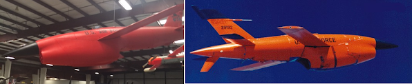
The Boeing B-52 Stratofortress, which ended up occupying the gas turbine-powered intercontinental bomber role which the Douglas 1211 would have fulfilled. 

For all its promising potential in terms of size, combat performance, and overall layout, the Douglas Model 1211 and parasite aircraft carrier versions of the Model 1240 would never progress beyond the drawing board. The Boeing B-52 by now had entered full-scale development along with the Convair YB-60 all-jet derivative of the B-36 Peacemaker, and the US Air Force certainly found the Model 1211  and Model 1240 projects too ambitious and too complex to be earmarked for full-scale development. In the meantime, the Soviet Union's Tupolev Tu-95 'Bear' turboprop bomber, utilizing the same design philosophy as the Model 1211, did proceed to the hardware phase, making its first flight on November 12, 1952, and it remains the only intercontinental bomber with turboprop engines in operational service, an anomaly considering that all other strategic bombers in service today are jet-powered.

[EDIT: Thanks to a copy of the revised edition of the American Secret Projects volume by Tony Buttler about bomber, attack, and anti-submarine aircraft designs from the 1945 to 1974 interval that I got recently, but also the comprehensive monograph by Zichek (2010), it is now clear that the parasite bomber designs intended for launch from the Model 1240 received the company designations Model 1251 and Model 1265. Although not exclusively a strategic bomber in the strictest sense, the Model 1240 was heavy enough to carry smaller aircraft and war material housed in underwing pods.]

References:

Buttler, T., 2010. American Secret Projects: Bombers, Attack, and Anti-Submarine Aircraft 1945 to 1974Hinckley, UK: Midland Publishing.

Buttler, T., 2021. American Secret Projects 4: Bombers, Attack, and Anti-Submarine Aircraft 1945 to 1974Manchester, UK: Crécy Publishing.

Remak, J., 2016. Boeing B-52 Stratofortress: Warrior Queen of the USAF. Stroud, UK: Fonthill Media.

Yenne, B., 2012. B-52 Stratofortress: The Complete History of the World's Longest Serving and Best Known Bomber. Minneapolis, MN: Zenith Press. ISBN 978-1610586726.

Zichek, J.A., 2009. The B-52 Competition of 1946…and Dark Horses from Douglas, 1947-1950 (American Aerospace Archive Number 3). La Jolla, CA: American Aerospace Archive. 

Zichek, J.A., 2010. Mother Ships, Parasites, & More: Selected USAF Strategic Bomber, XC Heavy Transport and FICON Studies, 1945-1954 (American Aerospace Archive Number 5). La Jolla, CA: American Aerospace Archive.

Thursday, April 8, 2021

Supersonic airliner designs from southern California

Much has been written about the Anglo-French Concorde and Tupolev Tu-144 supersonic airliners with some mention of the larger but unbuilt triple-sonic Boeing 2707 as well as 1980s and 1990s projects for new-generation supersonic airliners to replace the Concorde and Tu-144. However, almost lost in talk about supersonic civil aviation is the fact that a number of aircraft manufacturers in southern California were working on their own supersonic airliner designs, either comparable to or faster than the Concorde and Tu-144. Therefore, this post is tailored to discuss supersonic airliner projects conceived by the aircraft industry in southern California during the 1950s and 1960s.

Left: Lockheed CL-823 design, 1963
Right: Douglas Model 2229

In the late 1950s, a number of American aircraft manufacturers from southern California, including Lockheed and Douglas, conceived the notion of an airliner capable of traveling at supersonic speeds, fresh off their long-standing pedigree in airliner development. Before long, the delta wing had been selected as the best planform for high supersonic flight thanks to the transonic area rule developed in 1952 by aeronautical engineer Richard T. Whitcomb. Even though the aerospace industry was striving for the "higher, faster" realm of air travel, they had to confront one issue: unlike the delta wings of supersonic military aircraft, the most advanced wing designs for supersonic transports were around 9, in contrast to the wings of subsonic airliners. In 1958, Lockheed initiated design studies for a supersonic airliner capable of reaching Mach 3, including one with a tapered straight wing (similar to the one seen on the Lockheed F-104 Starfighter) and a delta canard, and another with a delta wing. However, these initial proposals were judged aerodynamically unsatisfactory judging from wind tunnel tests, and by 1962 a proposal was drawn up featuring canards and a highly swept cranked-arrow wing with four individual turbojets buried in the wings. In 1963, Lockheed unveiled a design for an SST with a double delta wing, called CL-823, which featured a double delta wing with an extended leading edge, a nose that could droop during landing, and four Pratt & Whitney turbofans arranged individually under the delta wing. The CL-823 was 223 feet (70 meters) long and could carry up to 210 passengers. Douglas's SST design study, the Model 2229, was similar to the B-70 Valkyrie but had a compound delta wing stretching from the single vertical rudder at the rear almost to the front of the fuselage, and it had an MTOW of 420,000 lb (190,508 kg) and a seating capacity for 100 passengers. Four turbojets were mounted in a nacelle under the wing that used two shock cones at the front of the intake, creating a single large duct with three-part variable-profile walls that slowed the intake air to subsonic speeds. Behind this duct were separate ducts leading to the engines, and the landing gear folded into space beside the duct. 


Left: Drawing of the Convair Model 58-9
Right: Artist's rendering of the North American NAC-60 in United Airlines colors

In the early 1960s, Convair and North American proposed the Model 58-9 and North American NAC-60 designs based on B-58 Hustler and B-70 Valkyrie supersonic bombers respectively. The Model 58-9, envisaged in 1961, was similar to the unbuilt B-58C (which Convair had proposed as a cheaper alternative to the B-70 Valkyrie) in the delta wing design and in having four Pratt & Whitney J58s (used on the SR-71 Blackbird) but differed in having an entirely new fuselage and tail empennage, and it had a length of 150 feet (45.72 meters), a seating capacity for 52 passengers, a maximum take-off weight of 190,000 pounds (86,000 kg), a range of 2,900 miles (4,600 km) and a speed of Mach 2.4. Convair saw the Model 58-9 as a follow up on route-proving using an unmodified B-58, with a version of the bomber using a five-passenger version of its unique external weapons pod being an intermediate step, and the first flight was planned for 1964, with expectations that the Military Air Transport Service would perform simulated airline flights with the Model 58-9. The NAC-60, on the other hand, had the delta wing planform and nose-mounted canards of the B-70 Valkyrie but differed in having a single vertical stabilizer, a less tapered fuselage, and a more compound wing. It was to be 195 feet (59 meters) long, with a wingspan of 121 feet (37 meters), a range of 3,900 miles (6,276 km), a top speed of Mach 2.65, an MTOW of 480,000 lb (217,724 kg), and accommodations for 187 passengers and four crew. 

Top: Lockheed L-2000 model at Planes of Fame Museum
Bottom: L-2000-7 full-scale mockup

On June 5, 1963, US President John F. Kennedy announced the launch of the National Supersonic Transport (NST) competition for a supersonic airliner with a top speed of Mach 3 while delivering a speech to the US Air Force Academy. The Federal Aviation Administration (FAA) sent out a Request for Proposals (RFP) to Boeing, Lockheed, and North American for the airframes, and Curtiss-WrightGeneral Electric and Pratt & Whitney for engines. The Lockheed CL-823 and North American NAC-60 were submitted to the FAA on January 15, 1964 along with Boeing's swing-wing Model 733 proposal; Convair's Model 58-9 failed to garner interest from the airlines and military and thus never left the drawing board, and Douglas chose not to enter the Model 2229 into the NST contest because it was financially preoccupied with the DC-8 and DC-9 jet airliners. As 1964 progressed, the NAC-60 design was rejected by the FAA due to it being slower and smaller than the Boeing and Lockheed submissions, and the CL-823 and Model 733 were selected for further design study. To meet a slate of revised requirements for the NST contest, in November Lockheed proposed the L-2000, of which three initial designs were worked out for Phase IIA studies: the 214 foot (65.23 meter) long L-2000-1 (170 seats), the 225.7 foot (68.8 meter) long L-2000-2 (221 seats), and the 245.7 foot (74.9 meter) long L-2000-3 (250 seats). The L-2000-1 and L-2000-2 were intended for intercontinental routes, while the L-2000-3 was optimized for domestic routes, and all were to be powered by four Pratt & Whitney JTF17 turbofans. During Phase IIB studies in 1965, a modified version of the L-2000-2 was envisaged as the L-2000-4, while the L-2000-5 and L-2000-6 had slightly cranked wings. By 1966, Lockheed unveiled its final design for the L-2000, the L-2000-7, of which a full-scale mockup was built at the Lockheed plant in Burbank. Two L-2000-7 variants were conceived, the L-2000-7A and L-2000-7B, both of which weighed 590,000 lb (267,600 kg), a larger delta wing, and an aerodynamic lift-to-drag ratio of 8:1, differing only in length and seating (the L-2000-7A was 273 feet [83 meters] long and carried 230 passengers, while the L-2000-7B was 293 feet (89 meters) long and carried 250 passengers).

On December 31, 1966, the FAA declared the swing-wing Boeing 2707-200 (an enlarged derivative of the earlier Model 733) the winner of the NST competition; the Lockheed L-2000, despite its simpler delta wing design, had slightly lower performance during takeoff and at high speed. The Boeing 2707-200, however, ran into developmental problems because tests with the swing-wing mechanism meant that the aircraft would be much heavier than Boeing engineers had expected, so in 1968, the Boeing 2707 was reworked into a slightly smaller delta wing aircraft, the 2707-300. Even so, the Boeing 2707-300 design faced opposition from environmentalists and the cost of making titanium for the aircraft was very astronomical, and in 1971, the Boeing 2707-300 was canceled without having flown.

Subsonic second-generation Firebee targets: the BQM-34A, MQM-34D, and BQM-34S

The Firebee drone series was the most prolific unmanned air vehicle family of the Cold War to be built in the United States, with its development spanning two generations and encompassing both subsonic and supersonic variants for a wide variety of combat and non-combat roles. However, the Firebees I have seen at aviation museums in southern California so far are quite different from the first Firebees to be built for the US military in their overall appearance, especially in having a scoop intake below the fuselage. Due to the staggering diversity of scoop-intake Firebee variants designed for subsonic and supersonic flight, I am confining the scope of this post to discussing second-generation Firebee target drone variants capable of subsonic flight.

Left: A BQM-34A drone on display at the Yanks Air Museum, photographed by me on May 19, 2018.
Right: A US Air Force BQM-34A in flight. 

In the late 1950s the Ryan Aeronautical Company envisaged the Model 124 design for an improved Q-2 Firebee drone with significantly enhanced flight performance. The airframe of the Model 124 was bigger and heavier than that of the first-generation Firebee, featuring a scoop intake below the nose, increased wingspan, a top speed of 690 mph (1,110 km'h), a 1,700 lb (7.6 kN) thrust. The Model 124 was formally designated Q-2C by the US Air Force (XQ-2, Q-2A, and XQ-2B were allocated to first-generation USAF Firebee variants), and the first XQ-2C prototype flew in December 1958 with production commencing in 1960. The US Air Force soon phased out the Q-2As as it took deliveries of the Q-2C variant, and the Q-2C was redesignated BQM-34A under a new Tri-Service guided missile designation system established by the Defense Department in June 1963. Meanwhile, the US Army replaced its first-generation Firebee (Army designation XM21) with a ground-launched variant of the BQM-34A, the MQM-34D (Model 124E), which had a slightly longer wingspan and a heavier RATO booster with greater duration as well as an endurance of 107 minutes. For its part, the Navy replaced its KDA-1 and -4 drones (redesignated AQM-34B and AQM-34C respectively) with the BQM-34A in 1964. The second generation subsonic target drone variants of the Firebee would be collectively called Firebee I to distinguish them from the supersonic Firebee II (BQM-34E/F/T), and production of the BQM-34A lasted until 1982.

Left: An MQM-34D Mod II showing the nose intake distinguishing it from the baseline MQM-34F.
Right: A BQM-34S after release from a DC-130 drone control aircraft.

In the early 1970s, the US Army wanted a high-performance target drone for realistic evaluation of the FIM-92 Stinger shoulder-launched surface-to-air missile. Teledyne Ryan thus envisaged an MQM-34D variant with an air intake in the nose for one General Electric J85 turbojet, designated Model 251 by the company. Initial flight tests of the Model 251 with the J85-GE-4 variant were only partially successful, but the Model 251 was able to attain the performance characteristics of the MQM-34D after being fitted with a J85-GE-7, and an unknown number of MQM-34Ds were upgraded to Model 251 standard, which was called MQM-34D Mod II and equipped with an M232 automated flight control system. The Navy upgraded its BQM-34As with the new AN/USW-3(V) ITCS (Integrated Tracking and Control System) flight control system in the mid-1970s, assigning the designation BQM-34S to these drones, which were re-engined with a 1,920 lb (8.5 kN) thrust J69-T-41A turbojet in the early 1980s. The Firebee I production facility in San Diego was reopened in 1986 for production of new-build BQM-34S drones, many of which were fitted with an upgraded A/A37G-8A flight control system. The US Air Force in the early 1980s upgraded its BQM-34As with a Vega DTCS (Drone Tracking and Control System) and an A/A37G-14 3-axis digital flight control system while having those drones re-engined with one J85-GE-7 turbojet. All BQM-34A/S drones in Air Force and Navy service were eventually upgraded with the 2,800 lb (12.45 kN) thrust J85-GE-100 by the early 1990s, and some of these drones were fitted with a GPS receiver for more precise navigator. 

More than 5,500 Firebee I target drones of all variants were built before the end of production in the late 1980s. The US Air Force continued operating the BGM-34A into the early 2000s, and five BQM-34As were used to lay corridors of chaff during the US invasion of Iraq in March 2003 after being modified by Northrop Grumman in February of that year to BQM-34-53 configuration; two were ground-launched and three were launched from a DC-130, and these drones were painted charcoal black to avoid enemy detection. The US Air Force eventually retired its remaining BQM-34As from service as the newer BQM-167 Skeeter began entering operational service, but the Navy still has a handful of BQM-34s in service, having upgraded them with new autopilot and navigation systems in the mid-2010s, although these are being phased out due to deployment of the newer Composite Engineering BQM-177.

The PV-2 Harpoon: the mechanized harpooner from Burbank

In late 1942, the Vega Division of Lockheed proposed an evolutionary derivative of the PV-1 Ventura (itself the US Navy variant of the Model...